

McIntosh Bass Luthiers
About
McIntosh Bass Luthiers is a two-generation shop. As father and daughter, Robbie and Helen McIntosh work side-by-side, specializing in high quality restorations and repairs using innovative and non-invasive techniques. They also build heirloom-quality handmade basses that will be played for generations to come.
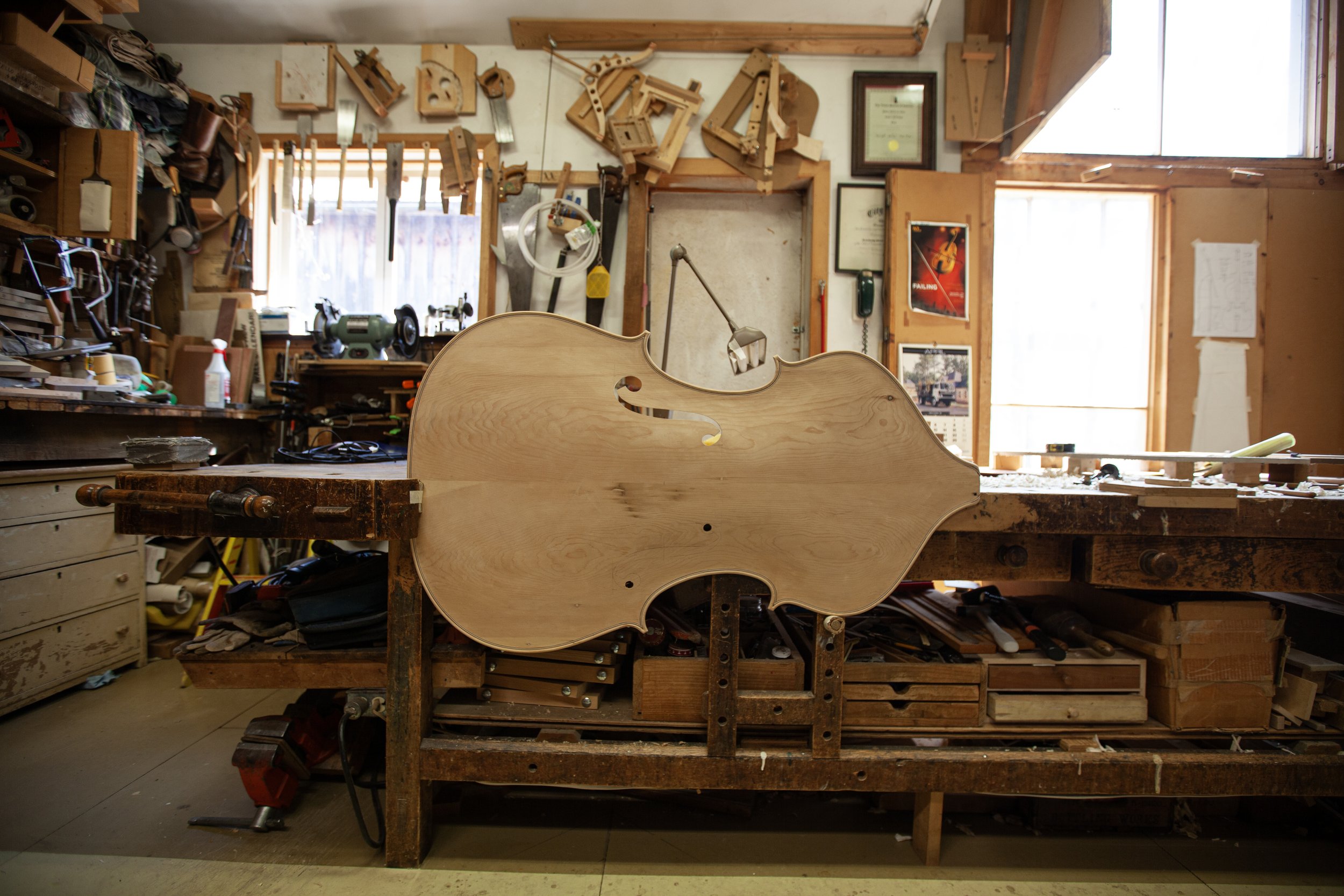
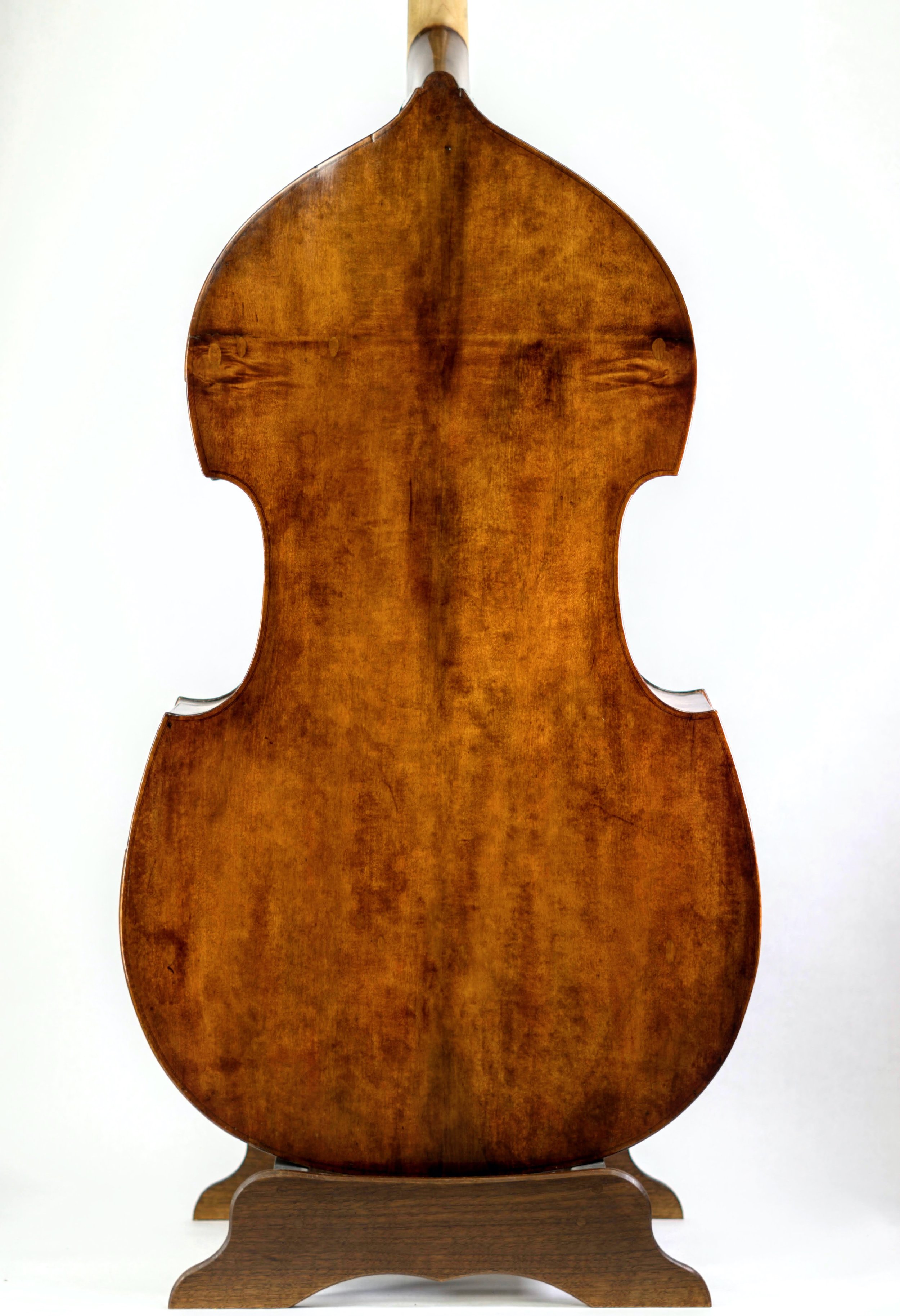
Handmade Basses
McIntosh basses are finely crafted from carefully selected and seasoned woods—some reclaimed wood from old buildings, some locally sourced lumber that has been sawn and seasoned to withstand the harsh extremes of the North American climate. They are modeled after venerable basses that have passed through the shop and have stood the test of time. All of our basses are set up to be easy to play by people of all genders, statures and body types. McIntosh basses have won several awards for tone in VSA and ISB makers competitions. You can purchase our basses directly from JD Hill Music.
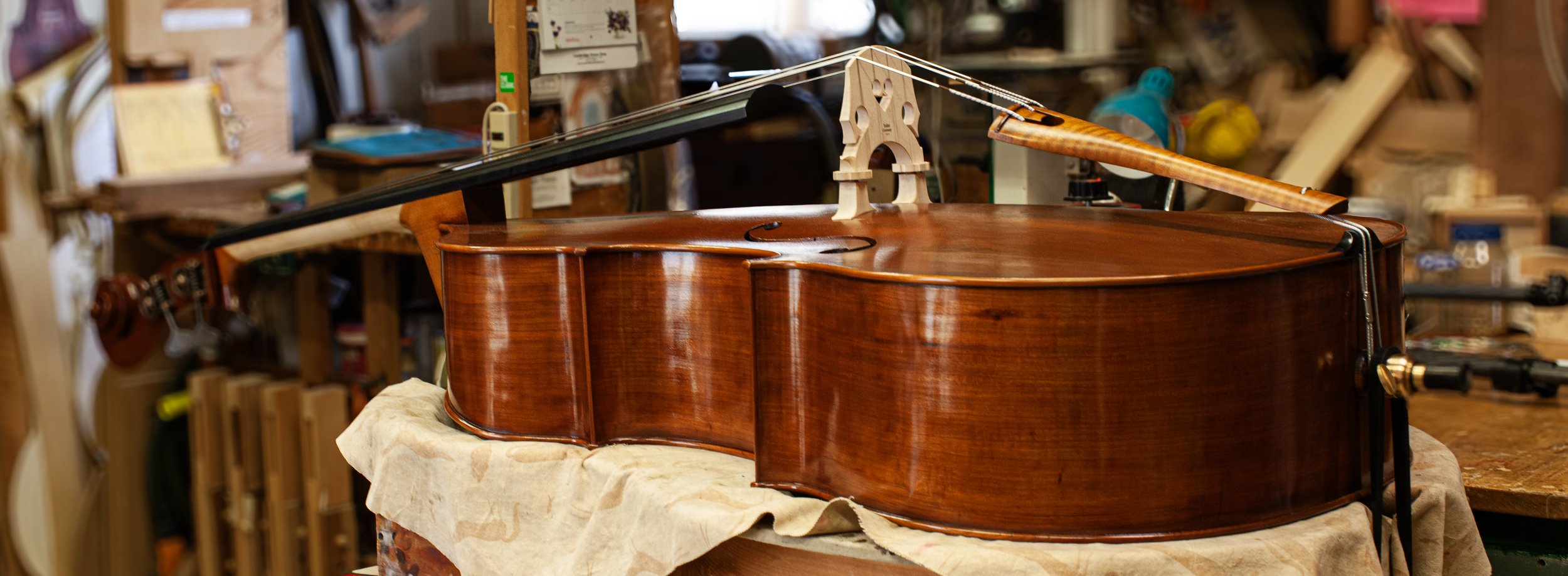
Restorations
Sometimes a bass has suffered so long from many “quick fixes,” normal wear and tear, and even abuse or neglect that it calls for a complete rebuild. There’s nothing that can’t be fixed, and a restoration can be an opportunity to modernize the geometry and setup of the instrument. In our experience, great basses sound even better when they are made “whole” again after a restoration.
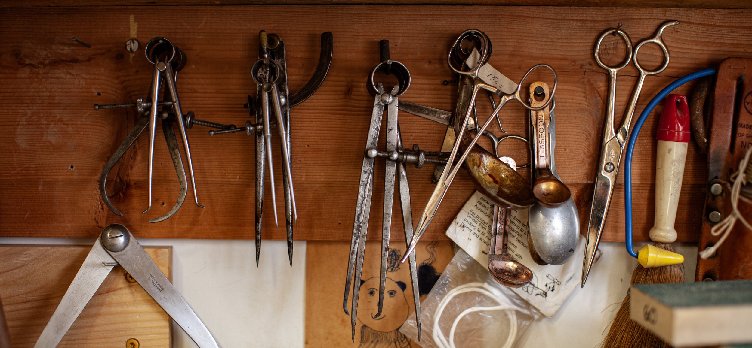
Repair & Setup
For students, professionals, and all bassists in between, a structurally sound and well-setup bass is central to a positive playing experience. When a need for repair arises, trust McIntosh Bass to treat your instrument with the care and expertise it deserves.
Robbie replaced the neck on my bass after an unfortunate fall. It has given my instrument new life and has increased its playability by measures unknown. He can make any bass sing to its full potential. I wouldn't think of having my bass worked on by anyone else.
—Dylan Perrillo
Contact Us
We’ll talk through any questions you have about a potential repair, restoration, or new bass commission.
Testimonials
“I am extremely grateful to Robbie for creating my bass. #9 has a very mature, warm, and powerful voice. She was old when she was brand new.
Robbie’s #9 bass has enhanced my sound profoundly making playing easier and more enjoyable. I continue to play a busy schedule of Operas and Symphonic concerts because it’s so much fun!”
— Brian Myhr
Owner of Robbie’s ninth bass, a 3/4 Italian model
Section Bassist for the Florida Grand Opera
Read Brian’s full testimonial here.
“The repair and restoration you’ve performed on my Busan is fantastic! Your technical skill is of the highest order but what makes your work truly exceptional is the patience and creativity you bring to the unique challenges of every project.”
— Jeremy McCoy
Assistant Principal Bass
Metropolitan Opera, Domenico Busan, 1749
“Thanks so much for the fantastic restoration of the Gabrielli!
Your careful planning and highest level of workmanship gave the best result possible! Guiding me through your plans for the restoration, sending me pictures several times a week and discussing different approaches over the phone kept me 100% updated. So, even though I live in Sweden I felt like I was in on every step of the restoration!”
— Hans Adler
Principal Bass
The Gothenburg Symphony Orchestra, National Orchestra of Sweden